Capacitance Meter Circuit Using 555
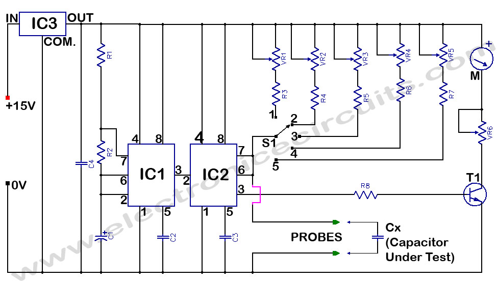
It directly reads capacitance in the range 100pF to 10µF. IC1 and IC2 operate as an astable (with frequency above 80Hz) and as a monostable multivibrator respectively. Time period of the monostable multivibrator is determined by the resistors (R3 to R7 and VR1 to VR5) selected by switch S1 and unknown capacitance Cx.

| PARTS LIST | |
| R1 | 12kΩ |
| R2 | 1.5kΩ |
| R3 | 820Ω |
| R4 | 8.2kΩ |
| R5 | 82kΩ |
| R6 | 820kΩ |
| R7 | 8.2MΩ |
| R8 | 10kΩ |
| VR1 | 1kΩ |
| VR2 | 10kΩ |
| VR3 | 100kΩ |
| VR4 | 1MΩ |
| VR5 | 1MΩ |
| VR6 | 100kΩ |
| C1 | 1µF 16V |
| C2 | 0.1µF |
| C3 | 0.1µF |
| C4 | 0.1µF |
| T1 | BC107 OR BC108A |
| IC1 | NE555 |
| IC2 | NE555 |
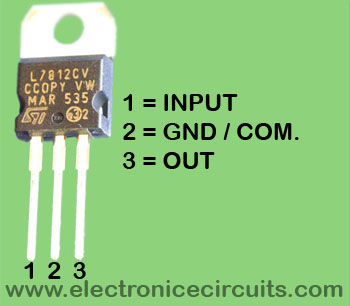
| IC3 | 7812 Regulator IC |
| M | 1mA f.s.d. Ammeter |
| S1 | 5way Switch |
By using high accuracy multi-turn presets the capacitance meter can be calibrated for the different ranges. Adjust VR6 so that the meter gives full scale deflection. Now the meter is ready for the calibration.
| RANGES OF S1 | |
| 1 | 1µF – 10µF |
| 2 | 0.1µF – 1µF |
| 3 | 0.01µF 0.1µF |
| 4 | 1KpF – 0.01µF |
| 5 | 100pF – 1KpF |
Cx should be 3.3µF, 0.33µF, 0.033µF, 3300pF, 330pF in ranges 1, 2, 3, 4 and 5 respectively for calibration. In each range the corresponding preset is adjusted to read 3.3 on the meter. Once presets have been set they should not be disturbed.

Electrolytic capacitor should not be used because of their wide tolerances. Supply should be well regulated.

Unknown capacitor is placed in the position of Cx and S1 is rotated to get a clear reading. It is not possible to go above 10µF as value of presets goes below IC555 specifications.
Please send your ideas, which are very important for our success…

I would appreciate more visual materials, to make your blog more attractive, but your writing style really compensates it. But there is always place for improvement
I really liked your blog! good
Very nice information.
Greatings, Nombre de http://www.electronicecircuits.com a GoogleReader!
Ilias
Interesante, no va a continuar con este artнculo?
Ilias
hi, can u please tell me how can i attach the 5 way switch or pin identification of 5 way switch
i have done this project .. i need to know the whole working of this project please help me.. its my mini project
Thank you for thes circuit