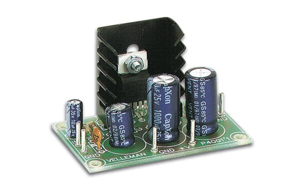
TDA2002 8w Car Radio Audio Amplifier
The TDA2002 and TDA2002A are integrated circuit amplifiers specially designed for use in car radios, where the adverse electrical environment places great demands upon the reliability of circuits.

| PARTS LIST | |
| R1 | 220Ω |
| R2 | 2.2Ω |
| R3 | 1Ω |
| C1 | 10µF 16v |
| C2 | 470µF 16V |
| C3 | 100n |
| C4 | 1000µF 25V |
| C5 | 100n |
| C6 | 100µF 25V |
| IC1 | TDA2002 |
| RL | 10W 4Ω |
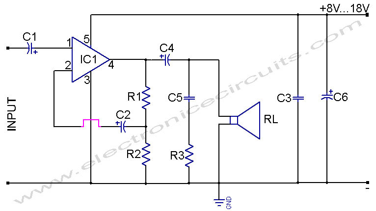
The supply voltage may be anywhere between +8 and +18V, and the IC will accept transient voltage peaks of up to 28V without damage. The IC can supply a short-circuit output current of 3.5 A and 15W of power at a case temperature of 90°C. At a supply voltage of 14.4V (fully-chargerd battery ) the maximum output power isat least 4.8W, and typically 5.2W into a 4Ω load.

The IC will, in fact, drive load impedances as low as 2Ω, in which case the maximum output power is at least 7W and typically 8W. The above power figugures are all measured at 10% distortion, but obviously at lower output powers the distortion is much less (Typically 0.2% ). In the circuit shown the gain of the amplifier is 100, determined by the radio of R1 and R2.

The heatsink for the IC should be 45 sq. cm of 3 mm thick aluminium, or a commercial heatsink of 8°C/W ( or less) thermal resistance may used.
Please send your ideas, those are very important for our success…
Hi increase C4 to 2200uF for 4ohms load, for a better LF response. 1000uF is ok for 8 ohms or higher load. This circuit is the best one rugged with low distortion and clarity.
in this 3 resistors how many watts use in this circuit??