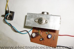
Low Ripple Regulated Power Supply Circuit Diagram
This circuit may be used where a high current is required with a low ripple voltage (such as in a high powered class AB amplifier when high quality reproduction is necessary ).
| PARTS LIST | |
| R1 | 2.2KΩ 1W |
| R2 | 56Ω 1W |
| R3 | 1oKΩ 1W |
| C1 | 1000µF 63V |
| C2 | 100µF 50V |
| C3 | 470µF 50V |
| D1, D2, D3, D4 | 6A Bridge Rectifier |
| D5 | 500mA Zener Diode (see description) |
| Q1 | 2N3055 |
| Q2 | 2N3054 |
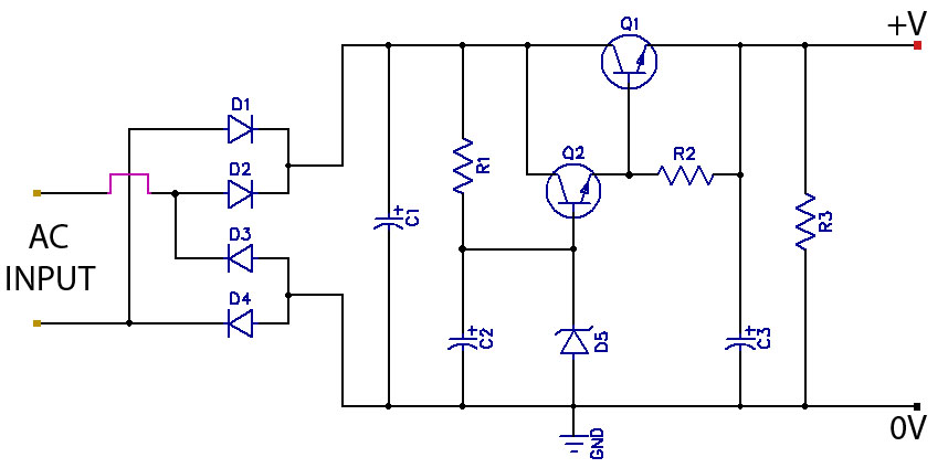
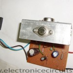
Q1, Q2, and R2 may be regarded as a power darlington transistor. D5 and R1 provide a reference voltage at the base of Q1. D5 should be chosen thus:
D5=Vout-1.2
C2 can be chosen for the degree of smoothness as its value is effectively multiplied by the combined gains of Q1/Q2, if 100µF is chosen for C2, assuming minimum hef for Q1 and Q2,
C=100×15(Q1)×25(Q2)
=37000µF.
Please send your ideas, which are very important for our success…
pls give me full diagream and write some details by that circuits and give it free or trayel varson.
thank u
does it works @ 24v power supply?
please gv information of bridge rectifier diodes
a transformer that converts 220v Ac to 12v Ac then rectifying circuit and then all the above elements , but the output voltage gets around 1.98v – 2v (tried every possible value for zener) , but if i do not use the transfomer part then i get 220v Ac to bridge ,which obviously would cause me to need power diodes of huge ratings and thus having a huge size ,(leaving heat losses and other things apart)… please let me know if u can help me get 12-30v Dc with input of around 12v 2A
i would like to attach the simulink file here but i dont know how to..
will wait for your reply
thanks
It’s very good to supply an power amplifier, because the capacitor it have high voltage.