LDR Light Detector Circuit using 741 Op-Amp
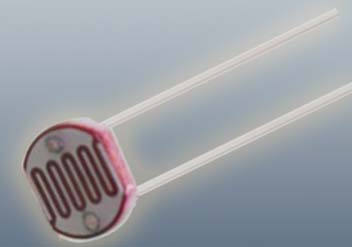
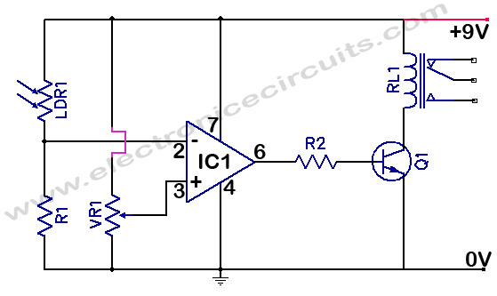
This LDR light detector circuit’s threshold is set by resistor VR1. When the intensity of the light falling on the LDR is lowered, resistance of that unit increases, and lowers the voltage applied to the inverting input of the 741.

| PARTS LIST | |
| R1 | 100kΩ |
| R2 | 100Ω |
| VR1 | 100kΩ |
| Q1 | 2N2222 |
| RL1 | 9V Relay |
| IC1 | 741 |
| LDR | |
The reference voltage at the noninverting input of the 741 is set (via Vr1) so that the comparator switch from low to high when the light falling on the LDR is reduced. That high activates transistor Q1, Which causes the relay contacts to close.
Please send your ideas, which are very important for our success…
Hi R2 should be 100 ohms not 100K ohms.
Thank you Seetharaman, I correct it.
great post as usual!
What a great resource!
Should be have the free wheeling diode?