Loudspeaker, Speaker Audio Power Indicator For Power Amplifier
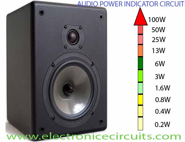
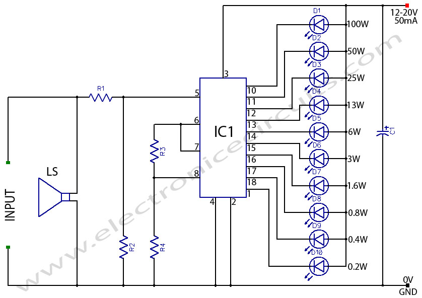
The LM3915 audio power meter with a bar-type read-out. The circuit has one drawback in that it requires a separate power supply. This is compensated, however, by the fact that it is pretty sensitive (0.2W min.) and does not degrade the sound quality in any way, since it does not present an additional load to the amplifier (in contrast, many inexpensive AF power indicators derive their display current from the amplifier).

| PARTS LIST | |
| R1 | SEE TABLE 1 |
| R2 | 10kΩ |
| R3 | 390Ω |
| R4 | 2.7kΩ |
| C1 | 22µF 25V |
| D1-D10 | LED |
| LS | Loudspeaker |
| IC1 | LM3915 |
The value of resistor R1 depends on the loud-speaker impedance as shown in the table inset in the circuit diagram. The resistor may be replaced by a wire link in the relevant position on the PCB if it can be fitted inside the plug that connects the indicator to the loudspeaker. This makes it convenient to use the indicator with loudspeakers of different impedance: use a dedicated cable for each impedance.
| TABLE 1 | |
| LS | R1 |
| 4Ω | 10kΩ |
| 8Ω | 18kΩ |
| 16Ω | 30kΩ |
For use with stereo systems, the circuit is either built in duplicate or the signals across the loudspeakers are applied to two series-connected resistor R1, whose common junction is connected to pin 5 of IC1. The latter method may raise some eyebrows, but it works fine in practice.
The power supply for the indicator is derived from a simple a.c. mains adaptor that provides a d.c. output of 12-20V.

Finally, it should be noted that the actual power measurement is an approximation only since the LM3915 reacts to the positive half-cycles of the signal only. This causes the top LED in the bar to light at a slightly reduced intensity.
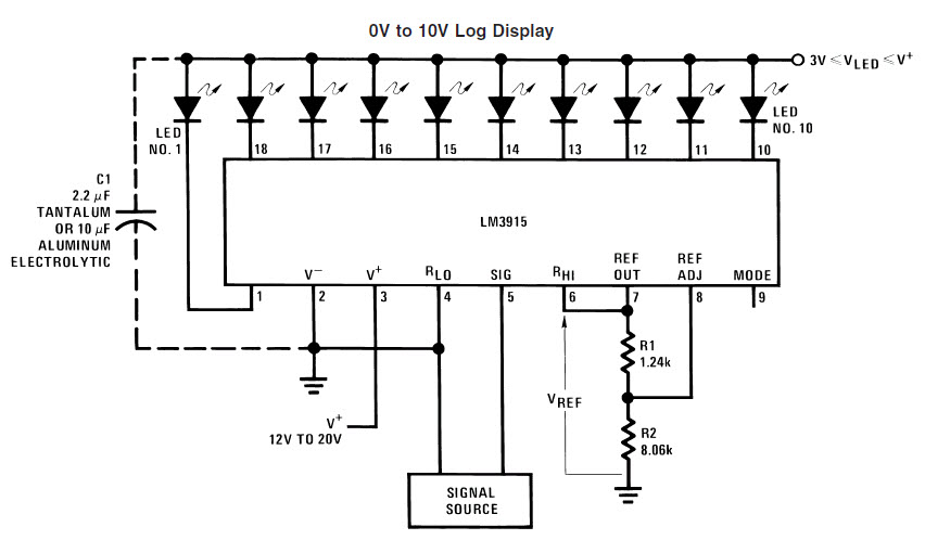
LM3915 IC DATA

Notes:
- Capacitor C1 is required if leads to the LED supply are 6″ or longer.
- Circuit as shown is wired for dot mode. For bar mode, connect pin 9 to pin 3. VLED must be kept below 7V or dropping resistor should be used to limit IC power dissipation.
- VREF=1.25V{1+(R2/R1)}+R2×80µA
- ILED=(12.5V/R1)+(VREF/2.2kΩ)
Please send your ideas, those are very important for our success…
can u send a copy of pcb layout.
This is excellent diagram. It is very easy to understand even an unknown person.