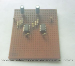
741 Stereo PreAmplifier Circuit Diagram
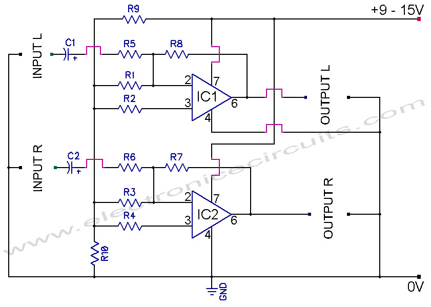
This preamp circuit provides better than 20dB gain in each channel.

| PARTS LIST | |
| R1 – R6 | 47kΩ |
| R7 | 1MΩ |
| R8 | 1MΩ |
| R9 | 2.2kΩ |
| R10 | 2.2kΩ |
| C1 | 0.1µF |
| C2 | 0.1µF |
| IC1, IC2 | LM741 |
This circuit design for single power supply. so it use resistor network to divide the voltage. this circuit they are R9 and R10. resistors R9 and R10 place a voltage of half of the supply voltage across the non-inverting input which causes the output voltage to also be half of the supply voltage forming a sort of bias voltage. R9 and R10 can be any value from 1K to 100K. but they need to equal.
A better op-amp type will give a better noise figure and bandpass.
In this circuit the roll-off is acute at 20000 Hertz.
Please send your ideas, which are very important for our success…


first post
Hello
thanks for this.
A couple of questions :
1.> Can 1x 1482 OP AMP be used instead of 2x 741 OP AMPs?
2.> What line out voltages will this produce, assuming this is used in a car with +12V power supply? Most power amps are looking for up to +5v line in signals. Want to make sure this isn’t going to blow the amp before I build.
Many thanks
Ash
Hi!
How can i control the gain of the amplifiers? I want to use a potentiometer. Which resistance would I have to replace with it?
I want add preamp Pls send sutable preamp circuit for you balance controll.
Bandwith? 20Hz to 20kHz? Is urgent, please reply
i think adding an 7805 bandpass filter in the circuit can reduce noise in the circuit
What is the output ??
thank you ^^