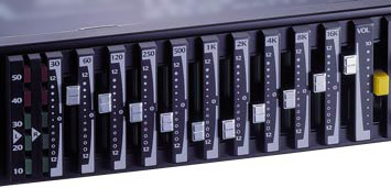
6 Band Graphic Equaliser Using 741 Op-Amp IC
With this circuit you can control and blend frequencies and tones as desired.
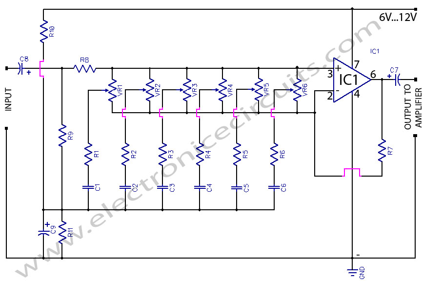
Essentially, the circuit consists of an IC 741 whose gain at various freguencies is determined by corresponding potentiometer setting.

The audiblefrequency spectrum is covered in six steps: 50Hz, 160Hz, 500Hz, 1.6kHz, 5kHz, 16kHz. All potentiometers are of 100kΩ linear type. The circuit provides adequate boost / cut for normal use.
| PARTS LIST | |
| R1, R2, R3, R4, R5, R6 | 27kΩ |
| R7 | 470kΩ |
| R8 | 330kΩ |
| R9 | 100kΩ |
| R10 | 4.7kΩ |
| R11 | 4.7kΩ |
| VR1, VR2, VR3, VR4, VR5, VR6 | 100kΩ |
| C1 | 100n (104) |
| C2 | 33n (333) |
| C3 | 10n (103) |
| C4 | 3.3n (332) |
| C5 | 1n (102) |
| C6 | 300pF (301) |
| C7 | 100µF 16V |
| C8 | 4.7µF 16V |
| C9 | 47µF 16V |
| IC1 | 741 Op amp |
power supply for the circuit can be derived from the amplifier / preamplifier itself. The wide rangeof supply voltage (6V-15V) makes the circuit very versatile. Power consumption is negligible.
Please send your ideas, those are very important for our success…
[img]tone control circuit[/img]
Hi, I’m using this circuit for my 1st year electronic engineering project, however I am picking up a lot of DC noise on my Oscilloscope as the wave produced is not smooth. Has anyone got suggestions how I can solve this problem ?
hi john the circuit isnt complete you shuld use like 10uf filer caps in your power seply
Hi cheers for the response, just going to try that now.
the body casing of the potentiometer should be shorted to the ground to reduce noise
hi, is this circuit complete?…thanks rob.