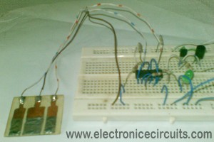
4011 Touch Control Switch Circuit
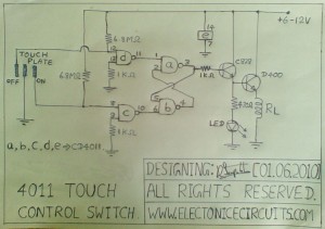
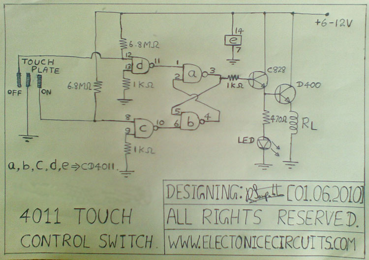
This touch control switch circuit designs by using two NAND gates and RS Flip-Flop.
4011 Touch Control Switch Circuit diagram
you can increase or decrease sensitivity by increase or decrease 6.8MΩ resistor values.
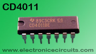 | 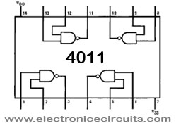 |
| 4011 QUAD 2-INPUT NAND GATE
All four positive-logic NAND gates may be used independently. On any one gate, with either or both inputs low, the output will be high; with both inputs high, the output will be low. | |
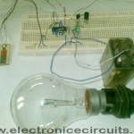
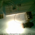
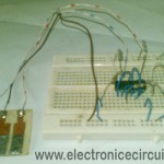
more images,
Please send your ideas, which are very important for our success…
this post is very usefull thx!
After reading this I thought it was very informative. I appreciate you taking the time and effort to put this post together. Once again I find myself spending way to much time both reading and commenting. But so what, it was still worth it!
You post informative articles, i have bookmarked for future referrence !
I love etectronic so i went to lean more.thanks for post