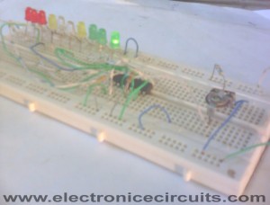
LM3914 12V Battery Monitor Circuit
This bar graph LED battery level indicator circuit is based on LM3914 monolithic IC from National Semiconductor that senses the voltage levels of the battery and drives the 10 light emitting diodes based on the voltage level that is detected.
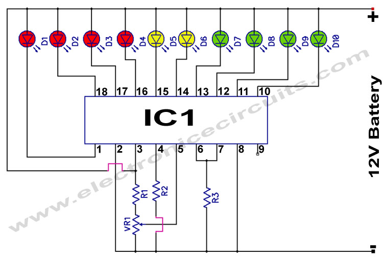
| PARTS LIST | |
| R1 | 56kΩ |
| R2 | 18kΩ |
| R3 | 3.9kΩ |
| VR1 | 10k Preset |
| D1 – D10 | LED |
| IC1 | LM3914 |
To calibrate the circuit it must be connected to an adjustable regulated power supply.
Connect an input voltage of 15 volt between the positive and negative poles and adjust the 10K preset until Led 10 lights up. Lower the voltage and in sequence all other Led’s will light up. Check that Led 1 lights up at approximately 10 volts.
This circuit to your own needs by making small modifications. The circuits above is set for ‘DOT’ mode, meaning only one Led at a time will be lit. If you wish to use the ‘BAR’ mode, then connect pin 9 to the positive supply rail, but obviously with increased current consumption.
The LED brightness can be adjusted up- or down by choosing a different value for the 3K9 resistor connected at pin 6 and 7.
You can also change the to monitoring voltage level.
For example, let’s say you wanted to change to 12 – 15 volt,
Remove the R2 resistor and connect 15volt to the input (+ and -) and adjust the 10K potentiometer until Led 10 lights up. Connect 200 Kilo-ohm potentiometer at pin 4 and -. Reconnect a voltage from 12 Volt to the input. Now adjust the 200K potentiometer until Led 1 lights up. When you are satisfied with the adjustment, feel free to exchange the 200K potentiometer with resistors again.(after measuring the resistance from the pot, obviously).
Please send your ideas, which are very important for our success…
Genial post and this mail helped me alot in my college assignement. Say thank you you as your information.
Thanks for posting, i learn more knowledge on electronics equipment and their uses. As i plan to set up mine but don’t have enough knowledge. At this time i do research more and more to learn everything. Good thing you have posted it. Have a great day! 🙂
Just want to say thanks for this circuit! I have a Radio Controlled Boat that I use for fishing and wanted a way of monitoring the battery and this little baby was spot on. Brought parts from Maplins for around a tenner.
hi , thanks a lot for this circuit it’s very useful ,
I just want to know if I can modify it for my 24Vdc
I have a 24Vdc and 12Vdc cigarette lighter in my CAB truck SCANIA , but I use a ( 0-30Vdc , 10A ) regulator
for my LAPTOP so I need the 24Vdc plug , that’s why
I need a 24Vdc discharge battery warner
thanks nice time
Hi, im a newbie at this and i need a monitor for my 4.6V dc battery from my cellullar that now has a different use. is there something special i should do for that circuit to work with my battery?
i made this cercuit. But four Red LED could not light up……..why?
i made this circuit but four Red LED could not light up……….why?
Thanx for the circuit,i needed it for a baitboat i made and i want to check the 12v battery i am using.
Hey – Thanks for the diagram. I’ve made this up and working perfectly for my 12v and 6v battery monitering.
Its pretty simple and well elaborated by the Author. GOOK WORK!!!
I have used R1=56K ohm,R2=33K ohm & R3=1.2K ohm.
Whenever I test a battery either 9 V or 3.7 V , then it always glows 9th LED.Why so?
Please feel free to tell me
Please if any one knows the answer,tell.
Please,
Can you build the types that can use 7 segment display instead of leds.
Thanks,
lanre
i need equivalent ic for ic LM3914………………..
I would like to make this also for monitoring my baitboat
Can you tell me the watt of the resistors please
Many thanks
REALLY IT WORKS . BUT WHY SHOULD RE-QUERIED MORE LED.
how to connect the terminals of |VR-1
thank you sir for this information
please can you help me to realize this project with 120V??
all my regards sir
hi, I am planning to build this to monitor my battery bank 12v 170ah, is it possible?
Hi i cant find the lm3914. Cut be posible use the lm393n?
You can’t use lm393n. It is a Dual Differential Comparator. Actually this type circuit can build up using comparators. But the circuit is more complicated. You can use this LM3915, LM3916, NTE1508 or NTE1549 alternative ICs. But circuit must slightly change.
Thanks!!!
Could you help me, I’m not electronic but I need this indicator for my battery bank
Thanks
Hey Admin, thx for your nice work, I really appreciate it!!
Could you tell, what in the circuit has to change, when it comes to LM3915?
And what about the potentiometer, is there a way to skip the calibrating part and directly use a resistor instead? How many Ωs would it need?
Thanks for your work, man!
And one more question: what do you need the R1 for? What would happen, if there was no connection between pole 3 and – …and only a resistor between pole 5 & 3 ?
Cheers!
i want to monitor the voltage level of a 24v battery its peak voltage is 27.2 and lowest voltage may be 22.5volts please give me resistance & variable resistance values please
i am really happy by this circuit, its very sample and useful for my project . i am thank for your .
a 12v battery has a Maximum operational voltage of 13.6v – 13.8v with a minimum of 10.5v. if you tell the circuit to read a max of 15v and a min of 10v you’ll get wrong info on the batterys health.
Just a small note about “12Volt” batterys. The typical lead acid battery which includes the traditional flodded and the various gell types. I am not including the more expotics like Li-on and its different fmilies because they require different charging regiment.
A 12 volt battery is NOT 12volts. It has a voltage range from 10.5v to 13.8v.
any voltage outside these ranges do nothing but damage them through sulfation and overcharging. Both of which can be easily spotted. Sulfation will appear like a growth on the plates, while overcharging will boil off the electrolyte creating hazardous hydrogen gas. Having a lead battery freeze is no fun either. When that happens you basically have a paper weight with a bulged, and, or, cracked case.
Lead acid batterys M U S T be kept at full charge at all times. period!
Lead acid batteries creat sulfate crystals during dishcharge and they attach them selves to the plates increasing their resistance and directly reducing their capacity.
Removing these crystals can be time consuming and mildly epxensive.
The simplest way to prevent them from premature death is to get a Proper 4-stage charger, that will charge them properly and keep them full and healthy.
Thanks
Rob
the reason i came here is because i am looking to hook up a 3914 so i can monitor my 36v battery pack (30-42v actually), but the pdf data sheets are terribly vague.
any thoughts ?
thanks
rob
can this circuit be edited to handle 24 volts
Hi.How to do it for 48V battery?
Everything is very open with a precise clarification of the issues.
It was definitely informative. Your site is very useful. Many thanks for sharing!
i like it.& i love you.
hey can u plz explain me the proper working principle of this circuit using IC lm3194
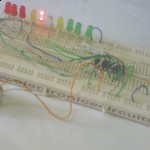
I made this and it turned out fine. I have calibrated using my solar batteries when fully charged. I will adjust to 15v when I get my variable power supply working. I like that this circuit not only gives me an indication of my battery status but also a visual indication when I am using something that draws a lot of current like a squirrel cage fan.
Hello! if I used 6v/4.5Ah battery, do I need to change anything in the circuit?
Thank you!
Hifirends.thanksfor circuit
I made this. I find it is extremely sensitive and that it gives me a good indication of voltage drop, especially on heavy battery loads.
I use it in place of the voltmeter I made to show me solar power input and battery voltage.
Now all I need is a box to put it in.
hi. can i ask a question? if it works at 24v sir? asap .. just for my thesis
asa,you don’t show any where the wattage of resister.confussion.
All resistors should be 1/4 Watts.